

back to listings SME Profile: ACS Aviation Industries Ltd
|
ACSAI Ltd, Unit 1, Swinbourne Drive, Springwood Industrial Estate, Braintree, Essex, CM7 2YP T: +44 (0)1376 331 123 | E: customerservices@acsai.co.uk | W: www.acsai.co.uk
|

About Us
ACS Aviation Industries is a UK CAA 145, EASA 145, FAA 145 approved repair station specialising in the maintenance, repair & overhaul of all Boeing and Airbus structural components.
Operating from a 25,000 sq ft purpose built facility located near London Stansted Airport and employing experienced and fully trained aviation technicians, ACS Aviation Industries is well placed to offer reliable and technically sound solutions within any customer agreed time frames & budget
Our commitment to customer service is what sets us apart from our competitors. From the moment that we receive a component into the building, the customer is kept fully informed of the progress of the part from inspection and quotation and then all the way through to the full certification of the component on time and on budget.
Why Us?
ACS Aviation Industries technicians all average 25 years of commercial aviation structural repair experience and will be able to provide an unsurpassed quality product allied with an industry leading turn-around time.
Services
ACS Aviation Industries Ltd provides inspection, repair and overhaul capability for a wide range of structural aviation components.
|
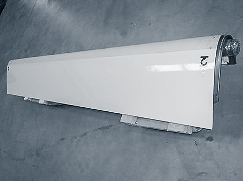
TRANSLATING SLEEVE |
THRUST REVERSERS |
INLET COWL |
 |
 |
|
|
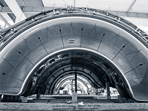
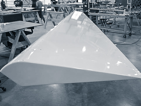
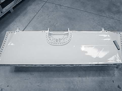
The translating sleeve forms the outer surface of each C-duct. In the forward thrust mode, the translating sleeve is held against the form of the C-duct. This gives an aerodynamically smooth surface to the engine nacelle. In reverse thrust mode, the translating sleeve moves aft on tracks near the top and bottom of the C-duct. As the translating sleeve moves aft it moves the blocker doors down and uncovers the cascade, which point the flow of fan air coming in to the duct outward and forward through the cascades. |
The purpose of the thrust reverser system is to provide a reverser thrust brake force for aircraft deceleration after the aircraft has touched down during landing. The system is a two-position one, with hydraulically actuated translating sleeves, mechanically moved blocker doors and static cascades. The thrust reverser system has four primary parts: the C-ducts, the translating sleeves, the blocker doors and the cascade vanes. |
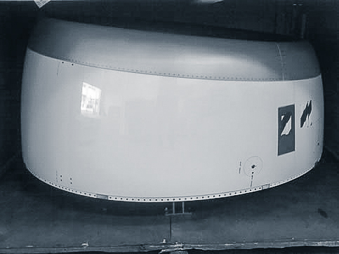
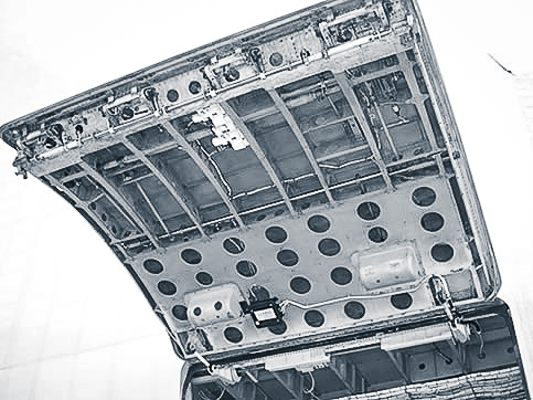
The air intake cowl directs air flow to the engine fan section. It also provides for a smooth airflow transition over the nacelle exterior surfaces. Acoustic panels on the intake barrel and or insulation blankets on the rear bulkhead of the air intake cowl, attenuate engine noise. A controlled hot engine bleed air is routed thru the anti-ice duct to the thermal anti-ice ring. The thermal anti-ice ring directs the controlled hot air flow to the inside of the lipskin to prevent ice buildup on the lipskin. The air intake cowl is attached to the front engine flange. The air intake cowl is attached to the front engine flange. |
|
FAN COWL |
ENTRY DOORS |
ELEVATORS |
 |
 |
 |
|
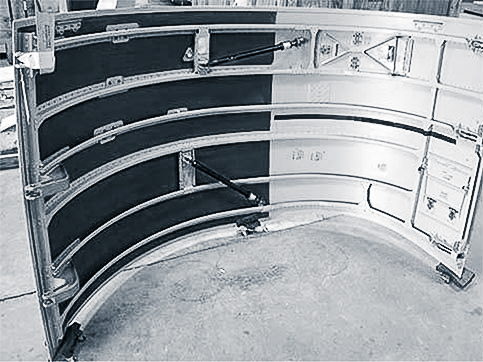
The fan cowls give an aerodynamically smooth surface over the engine, the engine mounted components and the accessories, as well as protecting them. Cooling air from the air intake cowl goes over the components and accessories to cool them. The fan cowls are attached to the pylon and align with the air intake cowl, the pylon fairing, and the thrust reverser doors. The cowls latch together at the engine bottom centerline and have seals at the joint. The front and rear edges of the fan cowls seal on the air intake cowl and the thrust reverser. |
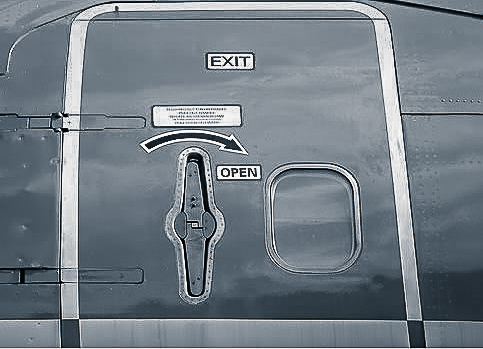
Main Entry passenger doors are generally outward opening hinged, plug type, pressure sealing doors. The doors typically have an upper and lower gate which unfold when the door is latched and closed. When the door is unlatched for opening the gates fold inward to allow the door to fit through the door opening. Generally there is a continuous pressure seal around the door periphery and in the gate hinge areas to prevent loss of cabin pressure. |
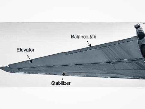
Elevators control the primary pitch of the aircraft. An aircraft has two elevators and the aircraft pitch attitude is controlled by these surfaces which are hinged on the rear spar of the horizontal stabiliser. |
|
CARGO DOORS |
GEAR DOORS |
FLAPS |
 |
 |
 |
|
Cargo Doors provide access to the aircraft cargo compartment. Generally a plug type door, with an inward opening structure hinged at the upper edge and is operated manually from either inside or outside the aircraft. Various access panels are located on the doors to provide for inspection or repair of the latching mechanism. |
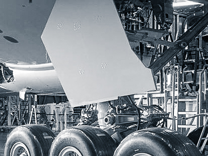
Gear doors are generally Metallic or Graphite/Fibreglass covered honeycomb structures that are attached to the gear strut. When the gear retracts the door closes the gear opening and creates a smooth aerodynamic fairing with the rest of the fuselage. |
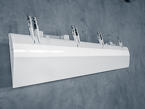
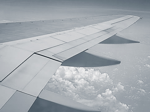
Trailing Edge Flaps provide extra aircraft lift during take-off and landing. When extended the flaps operate in conjunction with the leading edge slats to effectively increase camber and the area of the wings. Increased wing camber and area decrease stall speeds and allows the aircraft to be manoeuvred at lower speeds. |
|
SPOILERS |
RUDDERS |
WINGLETS |
 |
 |
 |
|
Spoilers are attached to the upper surface of the wing structure. They are used to provide assistance to ailerons lateral control and to also act as ground speedbrakes during landing. |
A rudder provides directional control and stability around the vertical axis. The rudder controls the yaw of an aircraft. |
Winglet devices increase the lift generated at the wingtip and reduce the lift-induced drag caused by wingtip vortices, thus improving lift to drag ratio. |
|
TABS |
AILERONS |
SLATS |
 |
 |
 |
|
In conjunction with aileron or elevator, the tabs are used to control the pitch or roll of the aircraft. Generally graphite/epoxy construction, with a front spar and attachment points. |
Ailerons, assisted by spoilers, provide lateral control of the aircraft. Most aircraft have two ailerons, one at the outboard trailing edge of each wing. Some larger aircraft also have inboard ailerons too. |
Leading edge slats are structural aerodynamic surfaces attached to the leading edge of the wing . When deployed slats increase the camber and area of the wing. Increased wing camber and area, decrease stall speeds and allows the aircraft to be manoeuvred at lower speeds. |
ACS, Proud Winners of the Queen’s Award for Enterprise 2018